Internet of Stranger Things

This year I’ve been running a workshop about using JavaScript and Node.js to work with all different kinds of electronics on the Raspberry Pi. So especially for 24 ways I’m going to show you how I made a very special Raspberry Pi based internet connected project! And nothing says Christmas quite like a set of fairy lights connected to another dimension1.
What you’ll see
You can rig up the fairy lights in your home, with the scrawly letters written under each one. The people from the other side (i.e. the internet) will be able to write messages to you from their browser in real time. In fact why not try it now; check this web page. When you click the lights in your browser, my lights (and yours) will turn on and off in real life! (There may be a queue if there are lots of people accessing it, hit the “Send a message” button and wait your turn.)
It’s all done with JavaScript, using Node.js running on both the Raspberry Pi and on the server. I’m using WebSockets to communicate in real time between the browser, server and Raspberry Pi.
What you’ll need
- Raspberry Pi any of the following models: Zero (will need straight male header pins soldered2 and Micro USB OTG adaptor), A+, B+, 2, or 3
- Micro SD card at least 4Gb Class 10 speed3
- Micro USB power supply at least 2A
- USB Wifi dongle (unless you have a Pi 3 - that has wifi built in).
- Addressable fairy lights
- Logic level shifter (with pins soldered unless you want to do it!)
- Breadboard
- Jumper wires (3x male to male and 4x female to male)
Optional but recommended
- Base board to hold the Pi and Breadboard (often comes with a breadboard!)
Find links for where to buy all of these items that goes along with this tutorial. The total price should be around $1004.
Setting up the Raspberry Pi
You’ll need to install the SD card for the Raspberry Pi. You’ll find a link to download a disk image on the support document, ready-made with the Raspbian version of Linux, along with Node.js and all the files you need. Download it and write it to the SD card using the fantastic free software Etcher5.
Next up you have to configure the wifi details on the SD card. If you plug the card into your computer you should see a drive called BOOT. There’s a text file on there called wpa_supplicant.conf. Open it up in your favourite text editor and replace mywifi and mypassword with your wifi details6.
network={
   ssid="mywifi"
   psk="mypassword"
}
Save the file, eject the card from your computer and plug it into the Raspberry Pi.
If you have a base board or holder for the Raspberry Pi, attach it now. Then connect the wifi USB dongle7 and power supply, but don’t plug it in yet!
Wiring!
Time to wire everything up!
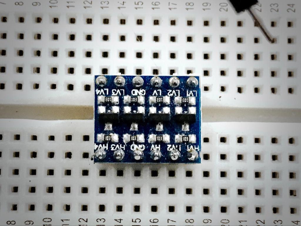
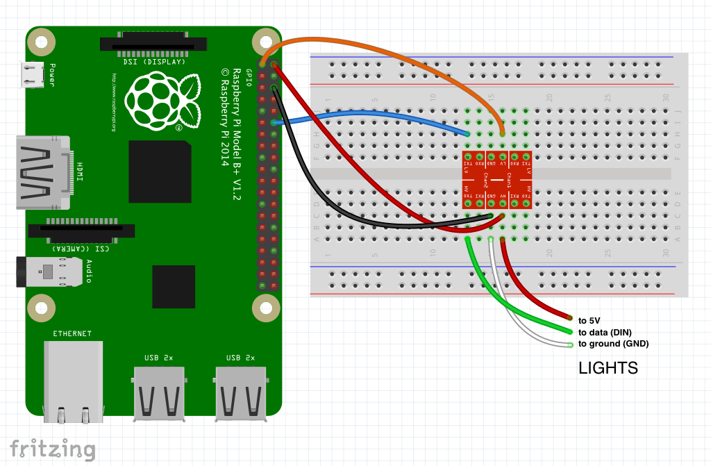
First of all, push the Logic Level Converter into the middle of the breadboard:
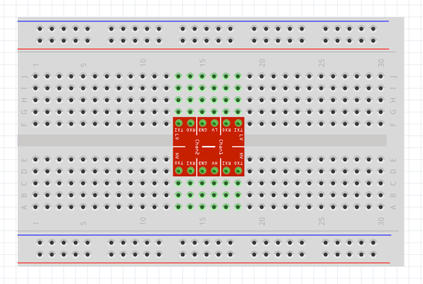
Logic Level Converter
The logic level converter may be labelled differently from the one in the diagram but the pins are usually exactly the same internally. I would just make sure the pins marked HV (High Voltage) are on the bottom and LV (Low Voltage) are on the top.
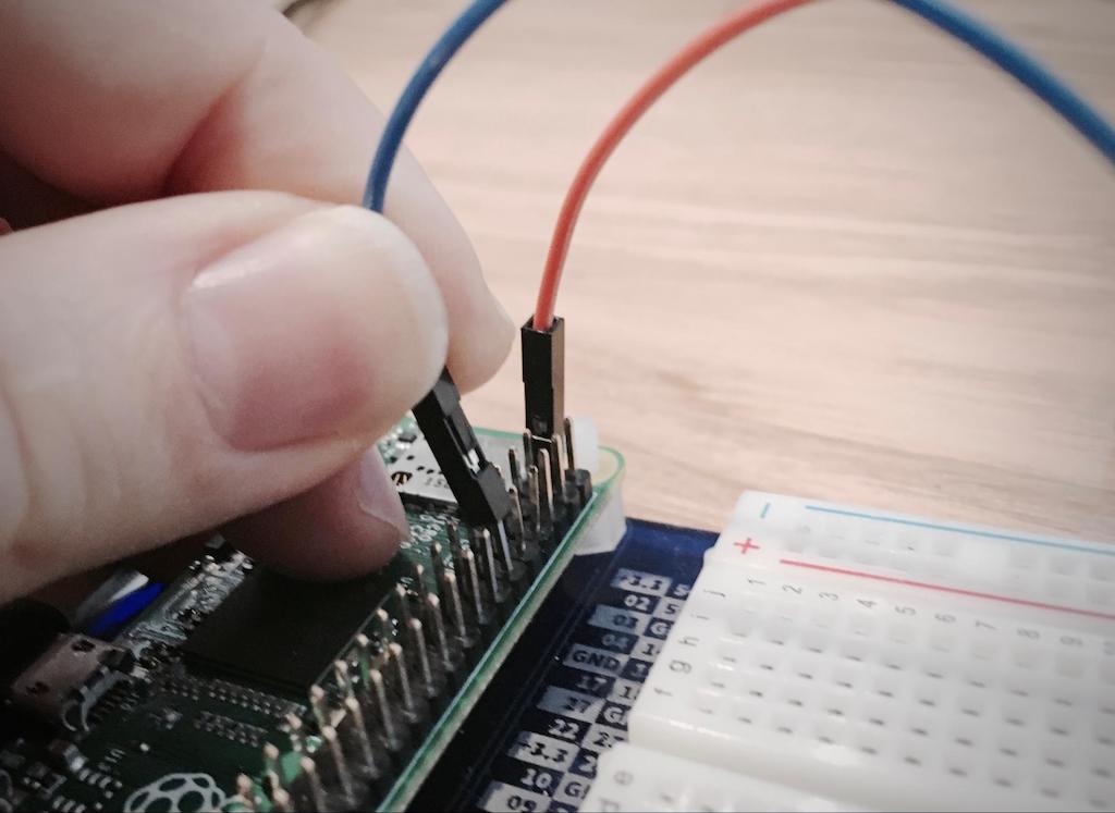
Connect the first two wires between the Raspberry Pi pins and the breadboard:
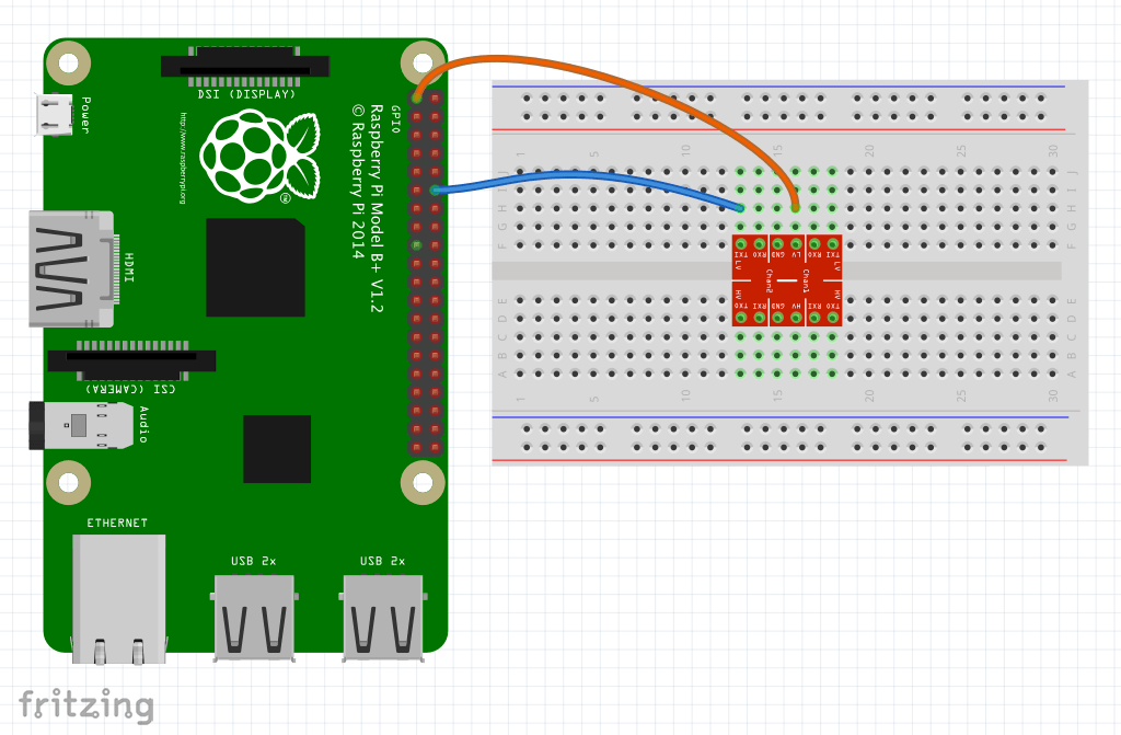
Note that the pins on the Raspberry Pi are male, so you need a female to male jumper wire to connect between them and the breadboard. The colours don’t have to match but it’s easier to follow (and check) if you use the same ones as in the diagram.
Then the next two:
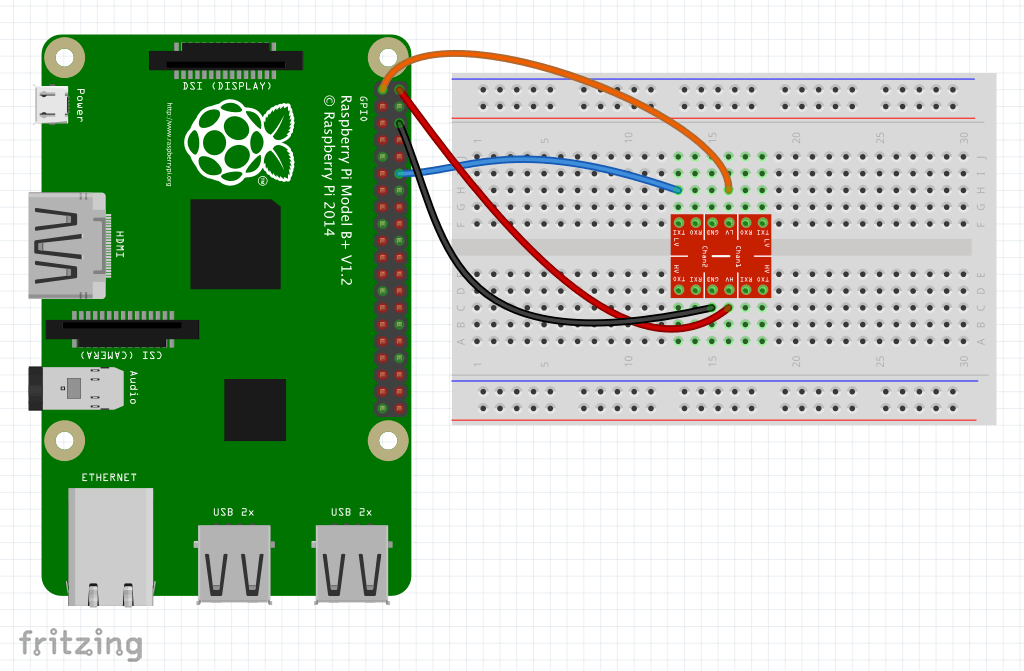
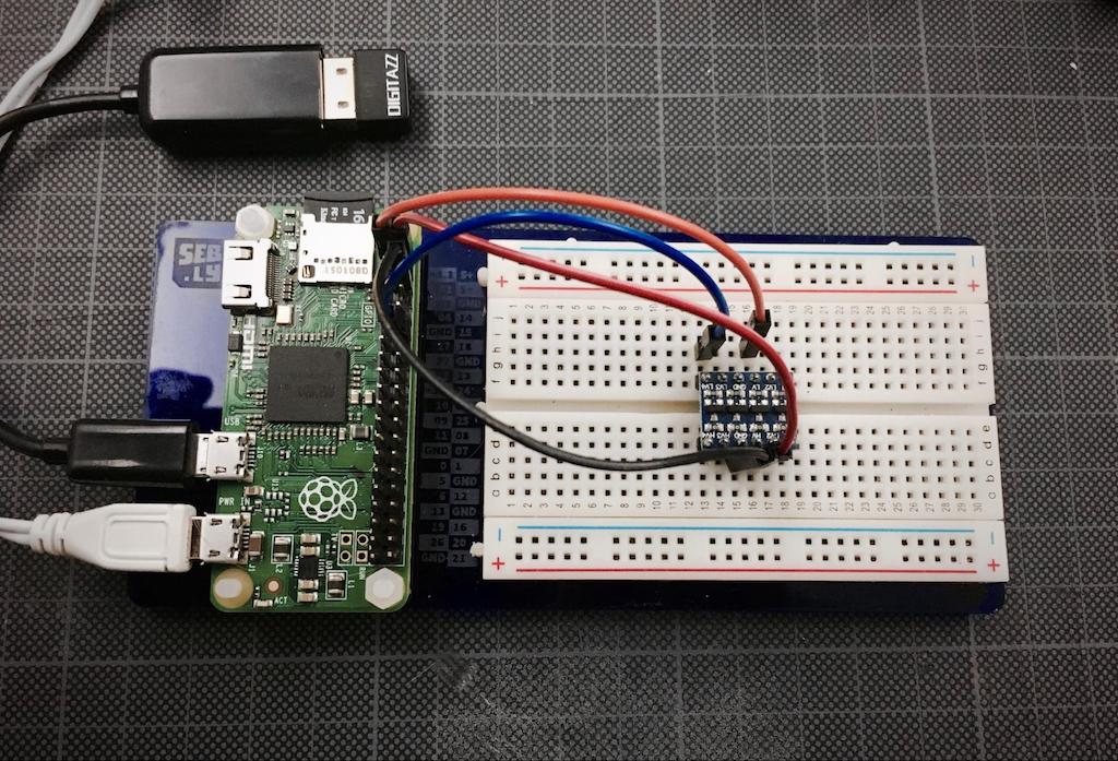
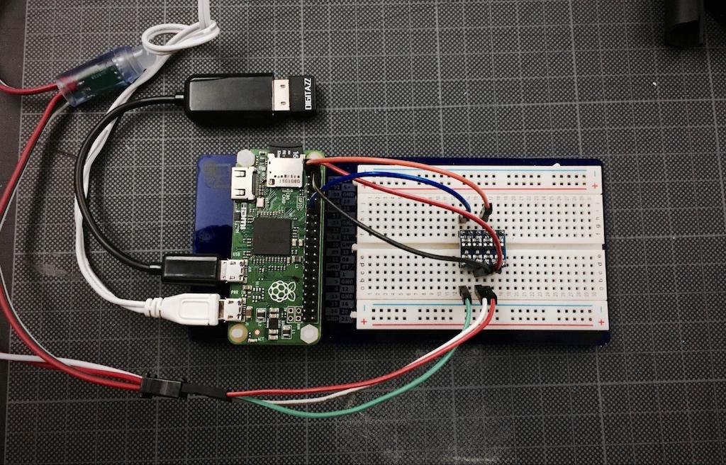
This is what you should have so far:
Lights
Now to connect the lights! My ones have a connector with three holes in it that I can push jumper wires into, and hopefully yours will too! So I used the male-to-male jumper wires to connect them to the breadboard.
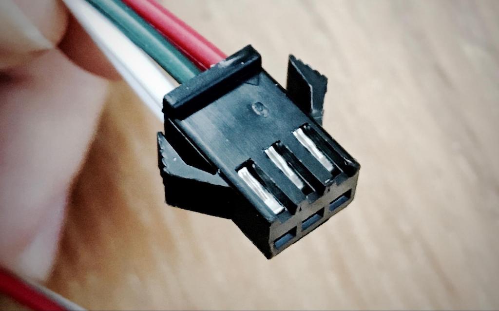
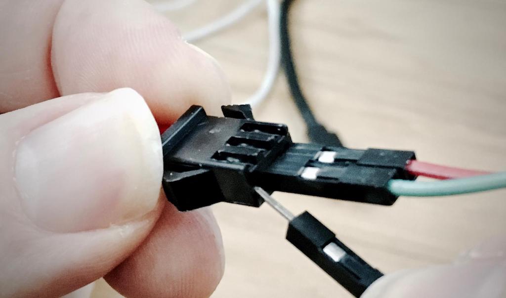
Make sure that you connect the right end of the lights, mine has a male connector at the wrong end so it’s impossible to do this, but double check.
Also make sure that the holes in the light connector are the same as mine. To do this, follow the wires from the connector to the first light and look at the circuit board inside. You should just about be able to make out the connections labelled + (sometimes 5V, V+ or VCC), GND (or ‘-’ or G) and DI (sometimes DIN for data in).
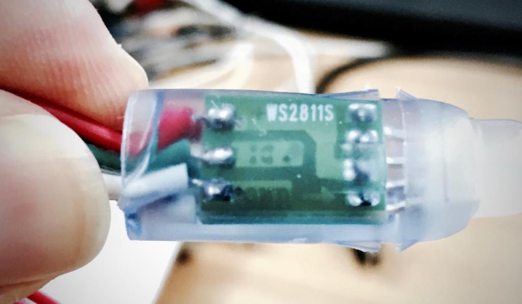
You can just about make out the +, DI and GND on this picture. Note that on the other side of the board there is a DO for data out - that’s what takes the data along to the chip in the next light. Make sure that you’re plugging into the data-in and not the data-out!
That’s it! Everything’s plugged in and ready to go! But before you plug power into your Pi, double check all your wires and make sure they’re exactly right! You could damage your Raspberry Pi if it is not wired correctly. So triple check!
The Moment of Truth!
Plug in the Raspberry Pi and wait around a minute or two for it to boot up. If all is well, the lights should strobe rainbow colours for one second - that’s your confirmation that it’s connected to my WebSocket server and ready to receive messages from the upside-down!
However, if the first light in the string is pulsing red, it means that you’re not connected to the internet. So check the Troubleshooting section of the support document. If it’s pulsing green then you’re connected to the internet but can’t connect to my server. It must have gone down. Sorry! The code will keep trying so leave it running and maybe it’ll come back up.
Rig up the lights!
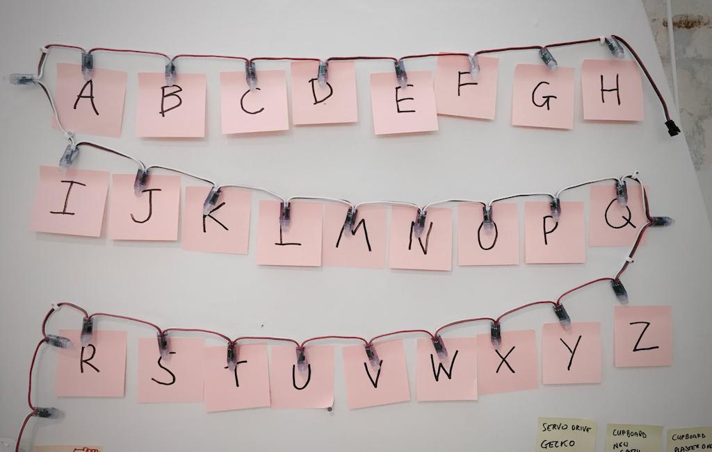
Fix the lights up on the wall however you want, pins, nails, tape. I’ve used cable clips. Just be careful! I’m using a 50 light string so I’ve programmed it to use the lights at the end for the letters. That way I have just under half the string to extend down to the floor where I can keep the Raspberry Pi.
Check the photo here to see how the lights line up, note that there are spare unused lights in-between each row:
Now visit lights.seb.ly and you’ll see this :
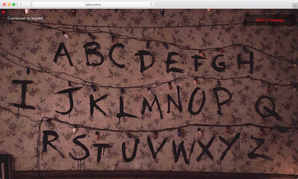
If you’re the only one online you’ll have direct connection to the lights and any letter you click on will light up both in the browser and in real life. If there are other people there, you’ll need to click the button to join the queue and wait your turn.
How it works - the geeky details!
Electronics:
The pins on the Raspberry Pi are known as GPIO pins, general-purpose input/output. You can connect a wide variety of electronic components to them, LED lights, buttons, switches, and sensors. You can turn the power to the pins on and off using Node.js (or Python, if you prefer).
Addressable LEDs or “Neopixels”
We’re only using one GPIO pin on the Raspberry Pi (the other connections are 5V, 3.3V and ground) and that single pin is controlling all of the lights in the string. The code turns the pin on and off really fast in strictly timed morse-code-like dots and dashes to transmit binary data. The chips attached to each LED decode the binary and adjust the output to the LED accordingly. That chip then sends the data on to the next light in the string.
The chips on each light are the WS2811, part of the WS281x family that come in a multitude of different form factors and are often packaged with tiny LEDs in a single component. They are commonly referred to as Neopixels8 and I used them on my Laser Light Synths project.
Logic Level Converter
The logic level converter is a really cheap and easy way to change the level from 3.3v to 5v and back again. You must be careful that you do not connect 5v into a GPIO pin or you will most likely damage the Raspberry Pi processor chip.
Power
Neopixels can often draw a lot of current so you need to be careful how you power them. I’ve measured the current draw from the string to be less than 800mA so you should be fine wired directly to the 5V output. But if you use more lights or have them all on really bright at once, you’ll need to use a separate 5V power supply. If you want to learn more, check out Adafruit’s Neopixel Uberguide.
Node.js
There are two Node.js apps running here, one on the Raspberry Pi and one on my server. You can see the code on my GitHub at github.com/sebleedelisle/stranger-lights for the Raspberry Pi and github.com/sebleedelisle/stranger-lights-server for the server. And they’re hosted on npm as stranger-lights and stranger-lights-server.
The server side code sets up a standard web server to deliver the HTML for the web interface. It also sets up a WebSocket server that allows for real-time communication between the browser and the server. This server code also manages the queue and who is in control of the lights at any given time.
WebSockets
I’m using the excellent Socket.io library to manage the WebSocket connection. Both the browser and the Raspberry Pi Node.js app connects to my WebSocket server.
When you click on a letter in the browser, a message is sent to the server, which forwards it to the connected Raspberry Pi clients and also all the web browsers9.
The Raspberry Pi code
The Node.js app runs automatically on startup, and I made this happen by adding this to the /etc/rc.local file:
node /home/pi/strangerthings/client.js > /dev/null &Anything in the rc.local file gets executed when the Pi boots up and this line of code runs the Node.js app and routes its output to nowhere (ie /dev/null). The & means that it runs it in the background and doesn’t hold up the boot process.
Working with the Raspberry Pi headless
You might know that when a computer has no screen or keyboard, you would refer to it as “running headless”. So just like most web servers, you need to configure it over the network with ssh10. If you’re on a mac you can find your Pi on the network through the name raspberrypi.local11, otherwise you’ll need to find its IP address. There’s more on the guide to Remote Access instructions on the Raspberry Pi website. And if you’re very new to the terminal, I highly recommend this great online Linux command line tutorial.
Improvements
This is quite an early experiment and I’m sure I’ll discover lots of optimisations over the next few weeks, especially if the server gets a proper hammering today! But there are a few things you can do. Obviously I’ve just rigged up my lights with Post-it notes. It’d be a lot nicer to get a paint brush and try to recreate the Winona-in-a-manic-state text style.
Where next?
Finding quality resources about Node.js for electronics on the Pi can be somewhat hit and miss, but this is getting better all the time. Alternatively I am thinking about running some online courses, please let me know if that’s something you’d be interested in, or sign up to my mailing list at st4i.com.
There are many many more resources for the Raspberry Pi with Python (gpiozero is a good place to start), so if that language works for you, you’ll be spoilt for choice!
Also take a look at Arduino - it’s an incredibly popular platform for electronics and the internet is literally bursting with resources.
I hope you enjoyed this little foray into the world of JavaScript electronics on the Raspberry Pi! If you get this working at home please let me know! Tweet me at @seb_ly.
-
Not a particularly original idea, but I don’t think I’ve seen anyone do it quite like this before, ie using WebSockets, and Node.js on a Raspberry Pi. Other examples: Internet of Stranger Things, Strangerlights.com, and loads of examples on Instructables ↩︎
-
Video guide to soldering pins on to a Pi Zero and further soldering advice from Adafruit ↩︎
-
Slower cards will work but performance may suffer ↩︎
-
Or £5,000 in UK money. Sorry, Brexit joke :) ↩︎
-
You will need a card reader on your computer - most micro SD cards come with an adaptor that fits standard SD slots. ↩︎
-
SSID and password should be all that you need but you can see all the config options on this wpa supplicant guide ↩︎
-
Raspberry Pi Zero will require the OTG to USB adaptor to attach the wifi dongle ↩︎
-
Thanks to Adafruit who invented the term neopixels so we don’t have to refer to them as WS281x any more! ↩︎
-
So you can see other people sending messages in the browser ↩︎
-
ssh is short for Secure Shell and is a way to connect to a remote computer and type in it just like you would in the terminal. ↩︎
-
You can change this default hostname using raspi-config ↩︎
About the author
Seb Lee-Delisle is a digital artist and speaker who uses computers to engage with people and inspire them.
As an artist, he likes to make interesting things from code that encourage interaction and playfulness from the public. Notable projects include Lunar Trails, featuring a 3m wide drawing machine, and PixelPyros, the Arts Council funded digital fireworks display that toured nationwide in 2013.
As a speaker he demystifies programming and explores its artistic possibilities. His presentations and workshops enable artists to overcome their fear of code and encourage programmers of all backgrounds to be more creative and imaginative.
His recent work Laser Light Synths won the 2016 Lumen Interactive Prize. He won 3 Microsoft awards in 2013, and he was Technical Director on Big and Small, the BBC project that won a BAFTA in 2009.